ABSTRACT Hard coatings deposited on micro drills and milling tools can effectively improve micro-machining qualityand processing efficiency. Diamond coatings, diamond-like carbon coatings and carbide/nitride coatings of transition metalhave been wildly applied in micro -tools, and boride coatings as well as oxide coatings, which have been utilized inconventional macro tools, are still in the development stage for micro-tools. The tool coating fabrication method includesphysical vapor deposition, chemical vapor deposition and atomic layer deposition. Based on the micro -drills and micro -milling tools, recently research progresses on pre-treatment, coating grain diameter, deposition parameter control as well asmicro tool fixture design are reviewed, which have guiding significance for the micro -tools coating deposition. With theoptimization and updating of coating fabrication method, the continuous evolvements of coating materials and structures haveled to the continuous improvement in the maximum hardness and service temperature of tool coating.
With the popularization of various products with small size and complex structure in aerospace, information technology, biomedicine, high-end electronic products, etc., it has greatly promoted the development of micro-nano manufacturing technology, of which micro-cutting is the key in micro-nano manufacturing Technology has attracted much attention. Micro-cutting refers to a mechanical micro-machining process method that uses a cutting edge with specific geometric features to remove material directly in a mechanical manner on a conventional precision machine tool or a small machine tool. Micro milling cutters and micro drills are the main micro cutting tools. The micro-milling cutter is mainly used for micro-milling, the diameter of the cutter is 25~1 000 μm, the length of the spiral groove is about 2~10 mm, the radius of the cutting edge of the cutter is about 20 μm; the micro-drill is mainly used for printed circuit board (PCB) Drill holes with a diameter of 20 to 1 000 μm. The main processing characteristics of micro-cutting are the tool wear caused by the “size effect” and the “grow pear effect”, and the tool bounce is serious, which leads to a decrease in tool life and low surface quality of the processed workpiece. Coating preparation on micro-drilling and milling tools is an effective way to improve the quality and efficiency of micro-cutting. The use of micro-drilling and milling tool surface coating technology that takes into account the requirements of strength, toughness and chip removal performance can greatly improve the tool life. It is beneficial to adopt a wider range of cutting speed and cutting depth in the process of micro drilling and milling, and at the same time improve the quality of the workpiece.
The base of the micro-drilling and milling tool is mainly made of high-speed steel, cemented carbide and diamond, cubic boron nitride and other super-hard tool materials, of which cemented carbide tools account for the largest proportion. Non-ferrous metals such as aluminum alloys below the micron level are mainly made of diamond tools, and micro-drilling and milling cutters for printed circuit board processing are mainly made of cemented carbide tools. In order to improve the performance of cemented carbide, tool manufacturers are currently researching fine-grained and ultra-fine-grained cemented carbides. They have developed ultra-fine grained cemented carbides with a particle size of 90 nm, and have trial-produced advanced grades with a particle size of 60 nm. Ultra-fine grain cemented carbide. In the process of micro-drilling and milling coated tools, the tool coating and the workpiece are in direct contact, the coating material and its preparation method directly affect the tool life and the quality of the workpiece. The fine tool has a small diameter and a complicated spatial structure, which makes it more challenging to apply a surface coating on its surface, especially near the cutting edge. Not only does the tool coating itself have superior physical properties, but the coating surface is smooth and compatible with the tool The matrix is well bonded. At present, the coatings of micro-drilling and milling tools are mainly divided into diamond, diamond-like carbon (DLC) coatings and transition group metal carbon/nitride coatings according to the coating materials; according to the structure, there are mainly gradient multilayer coatings and nanometers. Layer coating, nano composite coating, etc. Commonly used surface coating preparation methods mainly include physical vapor deposition technology, chemical vapor deposition technology, and atomic layer deposition technology.
1 Coating Material for Micro Drilling and Milling Tools
1.1 Diamond Coating
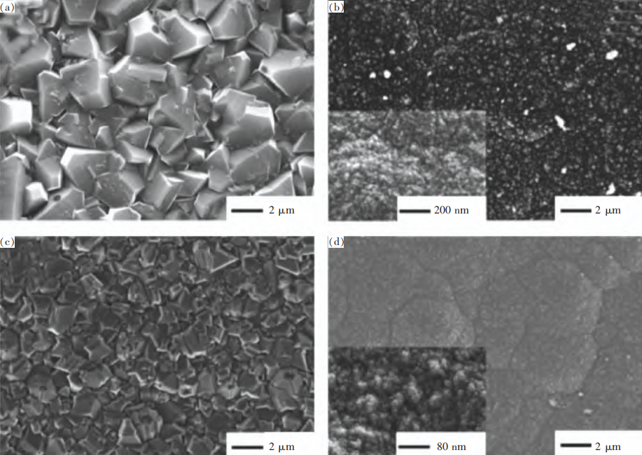
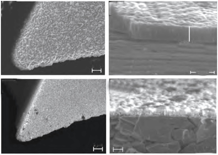
Diamond coating is an atomic crystal of carbon-carbon covalent bond hybridized with sp3. It has the advantages of high hardness, high wear resistance, low friction coefficient and low thermal expansion coefficient. It can be used in non-ferrous metals and alloys, non-metallic hard and brittle materials such as Precision machining of graphite, ceramics, fiber-reinforced composite materials, etc. A diamond coating with a crystal diameter of less than 100 nm is called “nano diamond coating” (NCD), and the thickness of the coating can reach 100-300 nm; a diamond coating with an average crystal diameter of 100 nm to a few microns is called “micron” “Diamond coating” (MCD) is generally used to ensure the continuity of the MCD coating. The thickness of the coating is greater than 2 μm. Figure 1 shows the surface morphology of MCD and NCD. Figure 2 shows the diamond-coated microdiameter of φ0.3 mm. The MCD coating has a larger grain size, grows in a column shape, and has a rough surface. The high hardness surface brings great difficulties to the subsequent polishing treatment; the introduction of the NCD coating can effectively solve the problem that the coating surface of the tool is too rough. The problem caused by the larger surface roughness of the processed workpiece, while the excellent toughness and wear resistance of the NCD coating can improve the tool life. Lei Xuelin’s research found that the diamond coating is too thin to protect the cutting edge, and the coating is too thick to make the edge passivated. For the φ0.4 mm printed circuit board microdrill, the 3 μm thick NCD coating Micro-drills have the longest working life, 5~7 times that of uncoated micro-drills. Torres et al. prepared NCD and fine-grained diamond coatings (FGD, crystal diameter 100~1 000 nm) on φ0.3 mm cemented carbide milling cutters. After processing 6061-T6 aluminum alloy, they found Only 40% of the NCD coating flakes off, while 80% of the FGD coating flakes off. On the other hand, the thermal stability of the diamond coating is poor. During the micro-cutting process, due to the fatigue load and cutting heat, it is easy to cause the graphitization of the diamond coating and accelerate the wear failure of the coated tools.
1.2 Diamond-Like Coating (DLC)
The DLC coating is an amorphous carbon-based thin film composed of sp2 hybridized carbon atoms, sp3 hybridized carbon atoms, and some heterogeneous atoms, which can be divided into hydrogen-containing amorphous carbon films (a-C:H) and non-crystalline There are two types of hydrogen-containing carbon film (a-C), because they have many properties similar to diamond coatings, and they can achieve low temperature and large area deposition. The deposition equipment is simple and the cost is low. Therefore, they are used in aerospace, automotive parts, biomedicine and other fields. have a broad vision of application. Based on the extremely low friction coefficient and self-lubricating properties of DLC coating, it is used for the cutting of graphite, non-ferrous metals, non-metallic hard materials (printed circuit boards, glass fibers, etc.). Figure 3 is φ0.3 mm DLC coated microdrills. The performance of the DLC coating is mainly determined by the internal bonding method and the ratio of various hybrid bonds caused by the preparation method and deposition conditions. The mechanical properties of the DLC coating are determined by the sp3 hybrid bonds, and the optical and electrical properties depend on the sp2 hybrid key. The presence of H atoms in the DLC coating affects the ratio of sp3 and sp2 hybrid bonds, which has an important impact on the film performance. The tetrahedral amorphous carbon (ta-C) coating is dominated by sp3 hybrid bonds, and its content is higher than 70%; in addition to the sp3 hybrid bond and sp2 hybrid bond, the hydrogen-containing amorphous carbon coating also contains certain Amount of H atoms, the content of sp3 hybridized carbon atoms is less than 40%. On the other hand, the internal stress of the DLC coating is large, the coating preparation and cutting process are likely to cause stress concentration at the cutting edge, causing chipping; the bonding strength of the DLC coating and the tool matrix is not high, resulting in the coating not easy to be thick and prone to occur Flaking; DLC coating has poor thermal stability. Due to the narrow chip flute of the micro-drilling cutter, it is difficult to evacuate chips, and it is easy to accumulate heat and cause the coating to fail. In order to improve the shortcomings of DLC coatings, currently doping metal elements or non-metallic elements, adding a gradient transition layer, constructing a multi-layer film structure, etc., to achieve the purpose of reducing the internal stress of the coating and improving thermal stability.
1.3 Transition Metal Carbon/Nitride Coating
The earliest appearance of tool coating materials is TiN coating and TiC coating, but with the development of modern processing technology and the diversification of processing materials, tool coating materials gradually follow a simple binary coating (TiN, TiC) → multiple Solution coating (TiCN, AlTiN, AlCrN, etc.) → multilayer or superlattice structure coating (TiN/TiC multilayer, TiN/AlTiN/TiN multilayer, TiN/AlN superlattice, etc.) → nanocomposite structure coating The direction of the layer (TiSiN, TiAlSiN, etc.) continues to increase, and the coating hardness and service temperature continue to increase. Among them, the CrN unit cell can dissolve more Al elements than the TiN unit cell, so the high temperature resistance is more excellent than the TiAlN layer, and it can still maintain the hardness of 27 GPa at 1 000 ℃. Aslantas compared the performance of cutting Ti₆Al₄V with φ0.5 mm NCD, AlCrN, TiN coated milling cutters and uncoated milling cutters. The surface roughness of the workpiece was the lowest when using NCD and AlCrN coatings, and when using TiN and AlCrN coatings The workpiece has the lowest burr width. Kang et al. studied the influence of Si element on CrN-based coatings. When Si≈9% (the content is atomic fraction unless otherwise specified), the hardness of CrSiN and CrAlSiN coatings can reach 35 GPa and 55 GPa; when Si≈8.7 %, of which φ0.1 mm CrAlSiN coated microdrill can achieve the best drilling performance. Adding Al element to the coating can produce a dense Al₂O₃ film during the processing to improve the oxidation resistance of the coating. By adding Si element to the coating, it is beneficial to form a composite coating structure of Si₃N₄ amorphous phase wrapped with crystalline phases such as TiN, CrN, etc., to improve the hardness of the coating, and at the same time to refine the grains, which is conducive to improving the coating’s fine cutting edge The wrapping ability guarantees the sharpness of the edge of the micro-drilling cutter. The use of nano-multilayer coating can further adjust the hardness and wear resistance of the coating, but the multi-layer structure is difficult to batch control, which is easy to cause uneven samples. It is not widely used.
1.4 Other
At present, there are still a large number of micro-drilling and milling tool coatings under development, such as boride coatings, oxide coatings, etc. CBN and diamond have similar crystal structure and lattice constant, have good heat resistance and wear resistance, and can cut titanium alloy in high temperature environment. The TiB₂ coating has high hardness and stable chemical properties, but its brittleness is relatively large, and its binding force is poor. Through the improvement of the preparation process, the design of the transition layer and the doping elements, the TiB₂ coating can gradually be applied to the microdrilling cutter上上. Gao Xiang found that the maximum hardness of the TiB₂ coating can reach 47.5 GPa by adjusting the workpiece bias voltage during preparation. The TiB₂ coating exhibits the best toughness by adding a Cr/CrN transition layer. Al₂O₃ coating has the advantages of high hardness, good wear resistance and high temperature stability, but its toughness is poor. At present, it is mainly used as a hard support layer on the top of traditional large-diameter tools. Studies by Zeng Xiangcai and others have shown that thick-film α-Al₂O₃ coated cemented carbide tools have excellent composite mechanical properties, which can significantly prolong tool life in high-speed, heavy cutting and difficult-to-machine materials.
2 Physical Vapor Deposition Technology (PVD) Preparation of Micro-Drilling and Milling Tool Coating Research
The physical vapor deposition technology is to evaporate or sputter the solid target material under vacuum conditions, and then ionize, recombine or react with the reaction gas to generate solid material and deposit it on the surface of the workpiece to form a uniform and dense coating. The use of PVD technology can achieve the deposition of hard coatings with excellent overall performance under low temperature conditions. In addition, PVD technology has obvious advantages in controlling the composition and structure of the coating. At present, tool coatings based on PVD technology have developed from simple binary single-layer coatings to multi-layer multilayer coatings and nano-composite coatings. The hardness and application temperature of coatings are constantly increasing.
However, there are still some key issues in the application of PVD technology in the coating of micro-drilling and milling tools:
- The edge coating will affect the radius of the blunt circle of the cutting edge of the micro drill and milling cutter, and it is easy to cause “pear cultivation” and “size effect”;
- The edge of the micro-drilling and milling cutter is small and sharp, which can easily lead to stress concentration and prone to chipping;
- The winding performance is not high, which is not conducive to depositing a coating evenly on the surface of micro-drilling and milling tools with complex shapes;
- Micro-drilling and milling tools have high requirements on the quality of the coating surface.
In the process of preparing the surface coating of micro-drilling and milling tools using PVD technology, the pretreatment of the tool, clamping and the specific PVD coating preparation process all have an important impact on the quality of the coated tool.
2.1 Pre-treatment
The pre-treatment of the PVD coating process is mainly surface purification. The surface of the workpiece is purified by cleaning, sandblasting and other methods to remove impurities and improve the quality of the surface coating. Due to the small diameter and poor rigidity of the micro-drilling and milling tools, it is easy to break away from the fixture and collide with the groove wall due to ultrasonic vibration in the line cleaning tank. Therefore, it is necessary to fix the fixture and the tool during cleaning. Ultrasonic cleaning agents generally include acetone, alcohol, or deionized water, etc. Acetone can remove grease on the surface of the tool, and alcohol can dissolve some surface impurities. The pretreatment process of traditional large-diameter tools generally includes sandblasting, but for fine drilling and milling tools, whether dry or wet sandblasting may damage the cutting edge, it is not recommended.
2.2 Clamping
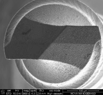
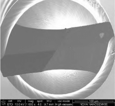
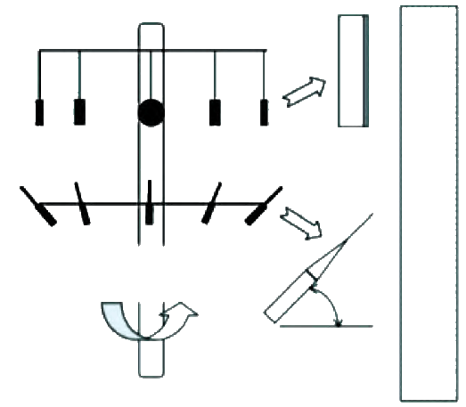
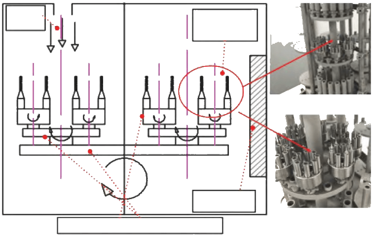
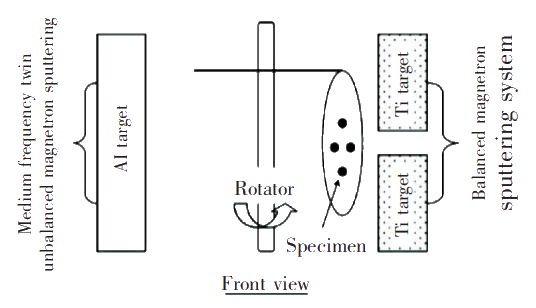
During the coating deposition process, the plasma concentration in the coating chamber is not easy to control, so the thickness of the coating across the micro-tools is often uneven. Yao et al. placed the microdrill at an angle of 45° during coating preparation, as shown in Figure 4, to make the coating more uniform. In addition, in industrial production, a three-dimensional rotating turntable is also used for clamping, so that the coating of the fine tool is more uniform, and it is also beneficial to increase the loading capacity, as shown in Figure 5.
2.3 Preparation Method of PVD Coating
After the pre-treated tool is sent into the vacuum coating chamber, there are still volatile impurities and surface oxides on the surface of the tool, which is not conducive to the combination of the coating and the tool substrate. Before depositing the coating, the active tool surface is generally etched using the in-situ plasma sputtering effect. Plasma cleaning can use gas ions or metal ions, of which gas ions are mainly inert gases, which can be doped with a small amount of hydrogen; metal ions are mainly cathode target particles, such as Cr, Ti, etc., metal ions are easily on the surface of the workpiece during etching Form a subsurface layer. For micro-drilling and milling cutters, high-energy ion bombardment can easily cause the tool to bend, which is not conducive to cutting processing, so low-capacity and high-density gas ion etching is a good choice.
Currently commonly used PVD coating preparation methods are mainly vacuum evaporation, arc ion plating and magnetron sputtering coating. Vacuum evaporation is not suitable for high melting point materials, and it has poor winding performance and low bonding strength with the substrate. It is generally not suitable for surface coating of superhard materials and complex workpieces. Arc ion plating and magnetron sputtering are widely used in the field of tool coatings. Among them, magnetron sputtering has developed balanced magnetron sputtering and closed field unbalanced magnetron sputtering according to different magnetic field arrangements and cathode target power supply forms. And high-power pulsed magnetron sputtering.
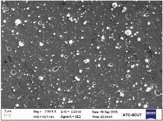
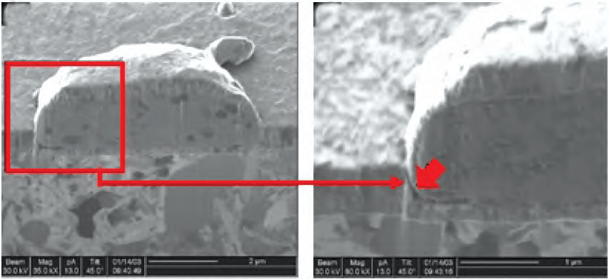
Arc ion plating is to form a cathode discharge spot on the surface of the target material by arc discharge in a vacuum environment, excite a large number of target particles, and then deposit on the surface of the workpiece. The biggest feature of arc ion plating is the fast deposition rate and high degree of ionization, which is conducive to improving the coating’s winding performance, density and adhesion, and greatly improving the production efficiency. However, in the arc ion plating process, after the cathode arc spot is ablated, it is easy to cause eruption of molten metal and produce “large particle” droplets. Due to the small diameter of the micro-drilling and milling cutter, the droplets on the surface of the coating have a great influence on the cutting performance of the micro-drilling and milling cutter, which can easily cause uneven force on the tool and also affect the surface processing quality of the workpiece. Figure 6 shows the Al₆₀Ti₄₀N coating deposited by arc ion plating. There are a large number of droplets on the surface. If the droplets are only on the surface of the coating, they can fall off through wear at the beginning of the cutting without causing problems such as poor surface quality of the processed workpiece. However, if the droplets penetrate the coating structure, as shown in Figure 7, it is easy to cause cracking or flaking of the coating during processing. Biermann et al. compared the cutting performance of five φ1.0 mm coated micro-milling cutters of CrN, TiN, AlCrN, AlTiN and TiAlN for cutting austenitic stainless steel X5CrNi18-10. From the perspective of workpiece cutting quality, the cutting quality of TiAlN coating is the most Poor, probably because TiAlN coated micro-milling cutters have the most droplets on the surface, resulting in a decrease in the quality of the workpiece surface. Regarding the “large particle” droplets in the arc ion plating process, most of the current research focuses on the use of blocking shielding, electric field suppression, process optimization, and magnetic field suppression to reduce or even eliminate large particle defects on the film surface.
Balanced Magnetron Sputtering Ion Plating (BMSIP) uses high-energy particles to bombard the target surface and sputter the target particles. By introducing a magnetic field on the cathode target surface, the movement time of electrons in the plasma is extended. A large amount of ions are ionized in the area to bombard the target, thereby increasing the deposition rate. However, due to the effect of the magnetic field, the plasma is confined to the target area of about 60 mm, which greatly limits the size of the workpiece and the amount of furnace installed, which is not conducive to industrial production. In addition, the energy of the balanced magnetron sputtering particles is low, the mobility of the deposited particles on the surface of the workpiece is low, and it is easy to generate a porous rough columnar crystal coating, resulting in a low binding force.
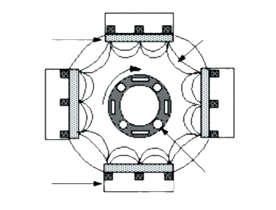
Closed-field unbalanced magnetron sputtering ion plating (CFUBMSIP) was developed by Teer in 1996 on the basis of traditional magnetron sputtering. The closed-field is formed by a magnetron system to increase the ion concentration, as shown in Figure 8, the plasma is expanded The body area helps increase the furnace load. Yao et al. used CFUBMSIP to prepare φ0.3 mm Zr-Ti-N coated microdrill for processing FR-4 (a kind of printed circuit board, mostly made of epoxy resin with filler and glass fiber) Composite materials), studies have shown that when the Ti content is 16.5%, the life of microdrills is increased by 2 times compared to TiN coated microdrills. By combining BMSIP and CFUBMSIP, Yao et al. prepared a φ0.3 mm TiN/AlN coated microdrill, as shown in Figure 9, the drilling performance of the microdrill also improved.
High-power pulsed magnetron sputtering (HIPIMS) uses a pulsed power supply for sputtering coating, using higher pulse peak power (2 to 3 orders of magnitude beyond traditional magnetron sputtering) and a small pulse duty cycle (0.5% ~10%) to improve the metal ionization rate. The metal sputtered by traditional magnetron sputtering is mainly in atomic state, which results in poor film-base binding force. The plasma generated by HIPIMS is highly ionized and has no large particles. The ion beam is accelerated by the bias of the workpiece Bombardment of the cutter base helps to remove the loose layer on the surface of the base and improve the coating adhesion. Thorton’s structural model shows that the bombardment of the substrate by the ion beam is beneficial to improve the surface diffusion ability of the deposited particles and improve the density and uniformity of the coating. In addition, HIPIMS technology improves the winding of the coating by improving the ionization rate, which is conducive to the coating of the cutting edge of the micro drill and milling cutter, while maintaining the sharp edge of the coating, the coating structure also changes from columnar to nanometer Crystalline transformation. Bugaev et al. used HIPIMS technology to deposit DLC coating, the sp3 bond content in the coating is 50%~60%, which is much higher than that of DLC coating prepared by traditional magnetron sputtering (≈30%), which is beneficial to improve the DLC coating. Hardness and wear resistance.
3 Chemical Vapor Deposition Technology (CVD) Preparation of Micro-Drilling Cutter Coating
The chemical vapor deposition technology uses plasma excitation, heating and other methods to make the reaction substances react chemically under certain temperature and gaseous conditions and generate solid substances to deposit on the surface of the substrate. The hard coating prepared by CVD has the advantages of high bonding strength and good winding plating. It is currently mainly used for the deposition of diamond coatings, diamond-like coatings and simple transition group carbon/nitrogen/oxide coatings. Deposition mainly uses CVD technology. However, CVD technology deposits diamond coatings on the surface of micro-drilling and milling tools. There are still some key problems:
- Deposition of the diamond coating requires removal of cobalt on the cemented carbide surface layer, and the diameter of the micro-drilling and milling cutter is small, and the removal of cobalt will reduce the rigidity of the cutter base;
- Temperature is the key to the CVD method. How to obtain a uniform and stable temperature field on a batch of micro-tools is critical. At the same time, the cobalt phase of the tool matrix diffuses under high temperature, which affects the adhesion between the diamond coating and the matrix;
- The edge of the micro-drilling and milling cutter is sharp, and the uniformity of the coating growth and the coating thickness have a great influence on the cutting performance;
- The control of the grain size, the precision of fine processing is high, and the grain size of the diamond on the surface of the coated tool has a great influence on the surface quality of the processed material.
During the preparation of diamond coatings using CVD technology, the pretreatment of the tool, seed crystals and specific CVD coating preparation process parameters all have an important impact on the quality of the coated tool.
3.1 Pre-treatment
For the preparation of tool coatings by CVD technology, in addition to the conventional surface purification treatment, for the preparation of diamond coatings on cemented carbide substrates, the presence of cobalt phases in high temperature environments will promote the graphitization of diamonds, so pre-cobalt removal treatment is required , Mainly using acid-base method. Generally, first use acetone ultrasonic cleaning to remove the oil on the substrate surface, then use alkaline solution to etch the surface WC phase, then use acid solution to etch the Co phase, and finally use deionized water to clean, so that the surface Co phase can be etched, increasing the substrate surface microscopic Defects, improve the nucleation rate and bonding strength of diamond coatings. The corrosion time of cobalt removal needs to be well controlled. Excessive etching can easily reduce the rigidity of the tool. Lei et al. used Murakami solution (V(KOH):V(K₃(Fe(CN)₆):V(H₂O₂)=1:1:10) and acid solution (V(HCl):V(H₂O₂)=30:70 ) Pretreatment, through optimization of the pretreatment time, it was found that the pretreatment time should not be less than 5 min. When the pretreatment time is 10 min, the cutting effect of the diamond-coated tool is the best.
3.2 Planting Crystals
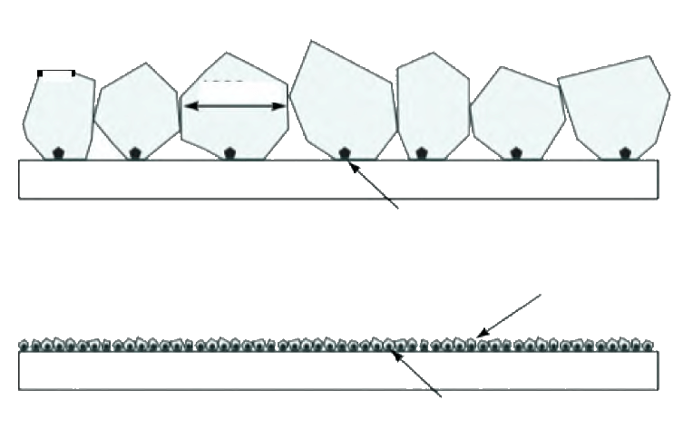
Planting crystals is a key process for the preparation of diamond coatings. After the cobalt removal treatment, the substrate is cleaned with a diamond suspension. The diamond powder embedded on the surface of the substrate forms a finite nucleation point during the growth process to promote the coating The epitaxial growth of diamond in the initial stage of preparation, while increasing the diamond nucleation density and film-based binding force. The seeding process of diamond coatings with different grain diameters is different, and the diamond crystal solutions used are also different. The fine crystal diamond coatings use DET (detonation nanodiamond) alcohol solution. The grain size is 20-50 μm, which can cover about 7.3% of the tool surface; the nanocrystalline diamond coating uses UDD (ultra-dispersed diamond) alcohol solution with a particle size of 20~300 nm, which can cover about 59.8% of the tool surface. Figure 10 shows the two solutions of DET and UDD Schematic diagram of planting crystals. Figure 11(a) is a fine-grained diamond (FGD) coating obtained by planting crystals with DET solution, and Figure 11(b) is an NCD coating obtained by planting crystals with UDD solution.
3.3 CVD Coating Preparation Method
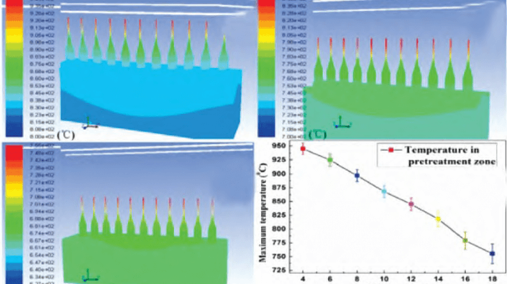
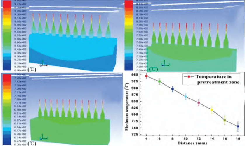
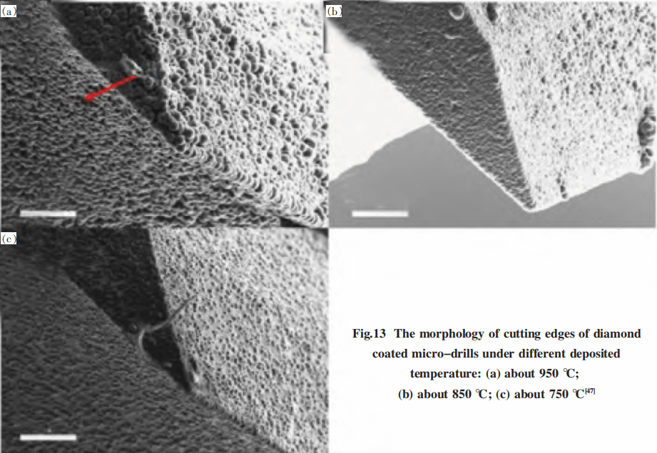
Commonly used process methods for preparing diamond coatings include hot wire CVD (HFCVD), microwave plasma CVD, DC arc plasma jet CVD, etc. The microwave plasma CVD method can produce high-quality diamond films with high purity and good crystalline morphology, but cannot deposit coatings on tools with complex structures. The diamond coating prepared by the DC arc plasma jet CVD method is of high quality, and is currently mainly used in the fields of microelectronics and optics. The HFCVD method has simple technical equipment, easy control of the process, high coating growth quality and appropriate rate, and is widely used in the tool industry. The HFCVD process mainly uses high melting point materials such as tungsten wire and tantalum wire to decompose carbon substances and activate chemical vapor reactions. Due to its simple equipment, relatively easy control of process conditions, and the quality of the deposited diamond coating, it is currently coated by diamond tools One of the most widely used methods in industrial production. For HFCVD, temperature control is critical. Lei et al [analyzed the temperature distribution of micro-drills with different diameters during the coating preparation process through simulation, and found that as the diameter increases, the temperature in the pre-treatment area of the micro-drills increases, as shown in Figure 12, and the φ0.3 mm The coating morphology of the drill at different deposition temperatures is shown in Figure 13. Heaney et al. used HFCVD to prepare a diamond-coated milling cutter with a diameter of 0.3 mm. Studies have shown that the temperature of the tool is affected by the distance from the hot wire. The temperature of the tool is too low, which hinders the growth of diamond. The coating is discontinuous and the temperature is too high, which is easy to form For more graphite phases, the recommended temperature is around 925 ℃. Song Bo et al. used the fluid dynamics simulation model to simulate the coating deposition temperature field, and obtained the optimal hot wire diameter, hot wire height, hot wire distance and hot wire length of the diamond coated microdrill (φ0.4 mm) prepared by HFCVD. On the other hand, current PCB drills of φ4.5 mm or more and PCB milling cutters of φ1.8 mm or more generally use solid carbide, and PCB drills of φ4.5 mm or less and PCB milling cutters of φ1.8 mm or less generally use Carbide blades are welded in the form of high-speed steel tool holders. In the process of coating preparation, excessively high temperature may easily cause deformation of the welded joint. When the diamond coating and DLC coating are prepared by CVD technology, the workpiece temperature can reach 700~900 ℃, so it is necessary to check the tool welded joint after preparation . The temperature can be controlled by adjusting the distance between the hot wire and the substrate, the temperature of the hot wire, the diameter of the hot wire, etc. when preparing the coating by HFCVD.
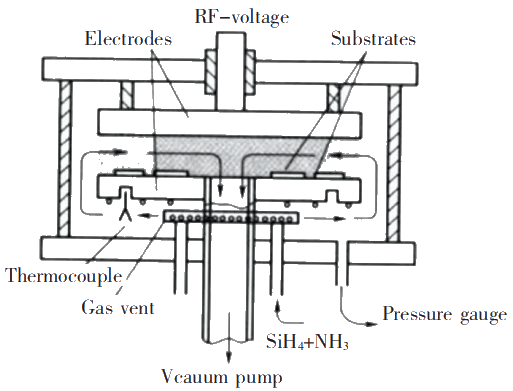
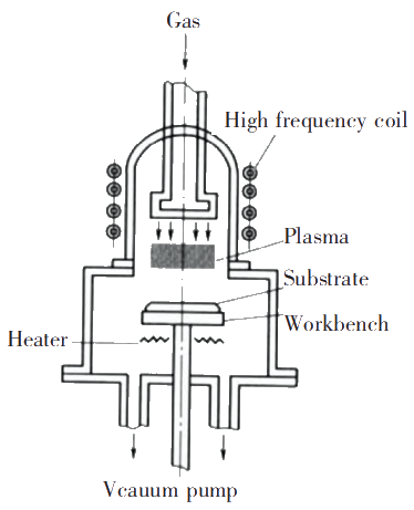
For simple transition group metal carbon/nitrogen/oxide coatings and DLC coatings, because the conventional CVD process requires a higher deposition temperature, and the micro-tools are very sensitive to temperature, the plasma enhanced chemical vapor deposition method ( PECVD). PECVD means that at a certain temperature, the reaction gas ionizes to generate plasma and interact with the surface of the substrate to form the desired solid film on the surface of the substrate. It relies on the energy of the plasma to activate the CVD reaction and utilizes the active chemical properties generated in the plasma. The ions and radicals can significantly reduce the substrate temperature and enable many reactions that are slow or impossible to proceed under other conditions. Figures 14 and 15 show two different structures of PECVD equipment. PECVD has the characteristics of low deposition temperature, large deposition area, and high deposition rate. It can coat films on complex shapes and large area workpieces. It can deposit uniform and dense high-quality thin films at low temperatures and room temperature, which can achieve mass production. Wu et al. used PECVD to prepare a DLC-coated micro-milling cutter with a diameter of 0.5 mm. The mixed gas of acetylene, argon, and tetramethylsilane was introduced, and the transition layer and DLC coating were prepared by adjusting the different ratios of the mixed gas. Cutting quality.
3.4 Other
Because various methods of removing the Co phase on the surface of the cemented carbide cannot completely eliminate the effect of Co on the growth of the diamond coating, because the temperature is higher during the preparation of the diamond coating by the CVD technology, the inner Co phase will diffuse to the surface layer again. Promote the graphitization of diamond. In recent years, a lot of research has focused on the transition layer of the cemented carbide substrate and the diamond coating. The single-layer transition layer generally uses a metal or non-metallic element that neither reacts with nor dissolves in carbon, or a metal or non-metal that can form strong carbides. Elemental metal, or carbide, nitride, such as Ti, W, Cu, TiN, CrN, Ti (C, N), Si3N4, etc.; the preparation process of single-layer transition layer is simple, the process parameters are mature, but with the modern micro-processing Continuous development and the emergence of a large number of difficult-to-process materials have gradually transformed into multilayer or composite transition layers, such as WC/W, TiN/TiCN/TiN, TiN/Mo, B/TiB₂/B, Ti-Si, etc.
4 Atomic Layer Deposition Method (ALD) Preparation of Micro Drilling and Milling Tool Coating
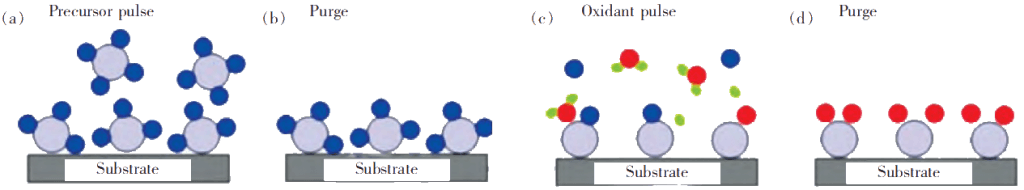
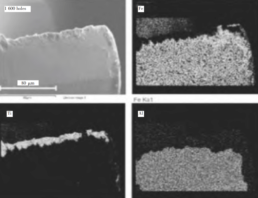
Atomic layer deposition is a method that can deposit substances layer by layer in the form of a monoatomic film. ALD technology is similar to ordinary CVD technology, but in the ALD preparation process, the chemical reaction of a new layer of atomic film is directly related to the previous layer. This method allows only one layer of atoms to be deposited per reaction. Therefore, it has high step coverage, excellent film composition control ability, and can accurately control the deposition thickness, as shown in Figure 16. At present, ALD is widely used in the fields of semiconductors, optical films, and nanomaterials. The use of ALD technology to prepare coatings on the surface of micro-drilling and milling tools is still in the research stage. Giorleo et al. used ALD technology to deposit a layer of Al₂O₃ on a φ0.5 mm high-speed steel microdrill with a thickness of 200 nm. The scratch test determined that the coating can withstand a maximum force of 60 N. After drilling titanium alloy 1 600 holes , The wear mainly occurs in the spiral groove, and the coating remains on the flank surface, as shown in Figure 17.
5 Conclusion
By summarizing the common problems of macro-cutting, combining the micro-cutting theory and the key points of micro-tool coating preparation, for different machining materials and working conditions, the preparation of special coatings for micro-drilling and milling tools has become the current research focus. Diamond coatings, diamond-like coatings, and transition group metal carbon/nitride coatings are widely used in micro-drilling and milling tools, and boride coatings, oxide coatings, etc., which are used on traditional large-diameter tools, The application of micro-drilling and milling tools is still in the development stage. For the PVD technology, the traditional arc ion plating and magnetron sputtering technology have been continuously improved, and the new coating prepared has greatly improved the durability and processing quality of the tool. Among them, the HIPIMS technology can effectively improve the coating surface finish and improve Coating performance may be the main development direction of coating preparation for micro drilling and milling tools in the future. For CVD technology, the preparation of diamond coatings to improve the coating adhesion strength and surface quality is the current research hotspot; the preparation of conventional transition metal carbon/nitrogen/oxide coatings and DLC coatings, low and medium temperature deposition is the future development direction. With the continuous development of modern micro-machining and difficult-to-machine materials, the combined use of different coating preparation technologies will bring new solutions to tool surface treatment.
Research on Coating of Micro Drilling and Milling Tools (II)