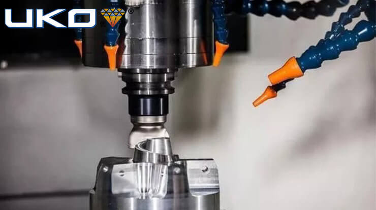
In CNC machining, the basic methods of tool setting include trial cutting, tool setting instrument setting and automatic tool setting. Today, take the CNC milling machine as an example to introduce a common trial cutting tool setting method. It is also called X-axis tool setting.
This method is simple and convenient, but it will leave cutting marks on the surface of the workpiece, and the tool setting accuracy is low. As shown in the figure, taking the tool setting point (here coincides with the origin of the workpiece coordinate system) at the center of the workpiece surface as an example, the bilateral tool setting method is used.
- Tool setting in x, y-direction.
- The workpiece is mounted on the worktable through the fixture. When clamping, the four sides of the workpiece should be reserved for tool setting positions.
- Start the spindle to rotate at medium speed, quickly move the worktable and spindle, so that the cutter tool quickly moves to a position close to the left side of the workpiece with a certain safety distance, and then reduce the speed to move close to the left side of the workpiece.
- When approaching the workpiece, use the fine-tuning operation (usually 0.01mm) to approach, let the tool slowly approach the left side of the workpiece, so that the tool just touches the left side surface of the workpiece (observe, listen to the cutting sound, see the cut marks, and see the chips, as long as If a situation occurs, it means that the tool touches the workpiece), and then retract 0.01mm. Write down the coordinate value displayed in the machine coordinate system at this time, such as -240.500.
- Withdraw the tool in the positive z direction to above the surface of the workpiece, approach the right side of the workpiece in the same way, and write down the coordinate value displayed in the machine coordinate system at this time, such as -340.500.
- According to this, the coordinate value of the origin of the workpiece coordinate system in the machine tool coordinate system can be obtained. {-240.500+(-340.500)}/2=-290.500.
- Similarly, the coordinate value of the origin of the workpiece coordinate system in the machine tool coordinate system can be measured.
- Z-direction tool setting.
- Move the tool quickly to the top of the workpiece.
- Start the spindle to rotate at medium speed, quickly move the worktable and spindle, so that the tool quickly moves to a position close to the upper surface of the workpiece with a certain safety distance, and then reduce the speed to move the tool end face close to the upper surface of the workpiece.
- Use the fine-tuning operation (usually 0.01mm) when approaching the workpiece, and let the tool end surface slowly approach the surface of the workpiece (note that it is best to cut the tool at the edge of the workpiece when the tool is especially an end mill, and the end surface of the tool is in contact with the surface area of the workpiece. If it is smaller than a semicircle, try not to place the center hole of the end mill under the surface of the workpiece), make the end face of the tool just touch the upper surface of the workpiece, and then raise the axis again, and write down the z value in the machine tool coordinate system at this time, -140.400 , The coordinate value of the origin W of the workpiece coordinate system in the machine tool coordinate system is -140.400.
- Input the measured x, y, z values into the storage address G5* of the machine tool workpiece coordinate system (usually use G54~G59 codes to store the tool setting parameters).
- Enter the panel input mode (MDI), enter “G5*”, press the start key (in automatic mode), and run G5* to make it effective.
- Check whether the tool setting is correct.