The increasingly urgent demand for tiny components and systems has been driving the development of micro-nano technology. In industrial production, micro-manufacturing is recognized as a key technology for manufacturing tiny products. With the development of micro-electromechanical system manufacturing technology, micro-manufacturing is widely used in medical engineering, communications, semiconductors and other fields. Among them, micro-cutting is an emerging frontier technology field in micro-manufacturing. It refers to a mechanical micro-machining process that uses a specific geometric cutting edge on a conventional precision machine tool or a micro machine tool to directly remove the material mechanically.
Micro milling cutters and micro drills are the main micro cutting tools that are different from ordinary milling tools. The micro milling cutter is mainly used for micro milling, with a diameter of 25~1000μm, a spiral groove length of 2~10mm, and a blunt cutting edge radius of about 20μm. Micro drills are mainly used for drilling printed circuit boards (PCB), with a diameter of 20~1000μm. Based on the main processing characteristics of micro cutting, coating preparation on micro drilling and milling tools is an effective method to improve the quality and efficiency of micro cutting.
Difficult-to-machine materials such as multi-layer printed circuit boards, titanium alloys, aluminum alloys, nickel-based alloys, and hardened steels have emerged in large numbers, bringing greater challenges to micro-cutting. Starting from the processing characteristics of various difficult-to-machine materials, this article reviews the research progress of micro-drilling and milling coating tools for various difficult-to-machine materials, and proposes suitable coatings for different difficult-to-machine materials. Layer applications are instructive.
1. Printed Circuit Board (PCB)
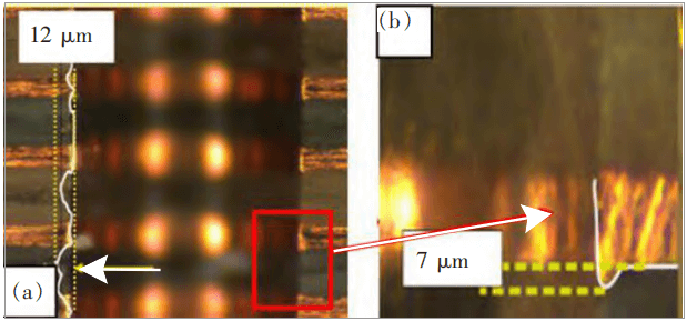
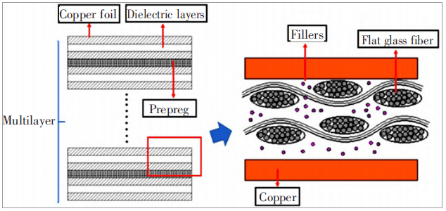
The printed circuit board (PCB) is the “nerve center” of the electronic system. It is responsible for the functions of signal transmission, switching, power supply, radio frequency, and bearing, and is the key core component of electronic equipment. The PCB is composed of copper foil, resin, hard filler and a variety of special woven glass fiber cloth. Its structure is shown in Figure 1. PCB cutting quality evaluation mainly focuses on hole wall quality, including nail head, hole wall roughness, etc., as shown in Figure 2. In addition, there are generally three criteria for tool wear.
The main processing characteristics of PCB are:
- The cutting temperature is relatively low. Huang Xin et al. used the temperature test paper temperature measurement method and found that the drilling temperature of a 0.25mm micro drill during the 20-layer PCB drilling process is about 127~143℃;
- The depth-to-diameter ratio of the micro-hole processing gradually increases (≥18:1), and the insufficient rigidity of the micro-drill leads to an increase in the deviation of the drilling, uneven force, and a decrease in life;
- A large number of high-hardness fillers (SiO2, AL2O3, talc, etc.) added to PCB cause severe tool wear;
- The resin of the dielectric layer is prone to sticking to the chisel edge due to the thermal coupling effect.
At present, coated micro-drilling and milling cutters for PCB processing are often used in some difficult-to-process PCB boards, such as high-speed boards, which have high hard filler content and severe wear on the tools; high-frequency boards, the main material of the dielectric layer is polytetrafluoroethylene ( PTFE), the spiral structure of PTFE material increases the distance of fluorine atoms, which makes the material soft and easy to deform, the coefficient of thermal expansion is large, and the drilling temperature is increased; the metal substrate contains copper or aluminum base, the cutting temperature rises, and the knife sticks seriously.
Commonly used coatings for PCB processing include diamond coatings, diamond-like carbon (DLC) coatings, TiN-based and CrN-based coatings containing Al and Si.
Diamond coating is the most commonly used coating in PCB micro-hole processing. It has excellent wear resistance: “with a lower friction coefficient”. Lei Xuelin used nano-diamond (NCD) coated balls with PCB boards for ball-disk Experiments have found that the friction coefficient between the NCD film and the PCB board is the lowest and the material removal rate is the highest.
In addition, the diamond coating can reduce the grain diameter by refining the crystal. The smaller the grain diameter, the more conducive to reducing the surface roughness of the coating and improving the cutting edge wrapping ability of the fine tool. When the crystal diameter is less than 100nm, it is called “Nanocrystalline diamond coating”, the thickness of the coating can reach 100~300nm; the diamond coating with an average crystal diameter of 100nm to several microns is called “microcrystalline diamond coating” (MCD).
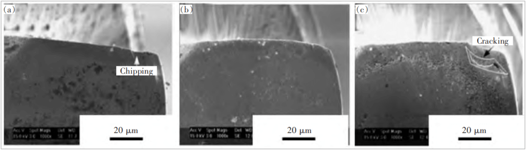
The φ1.0mm diamond-coated micro-drills were prepared by CVD with a thickness of about 13μm. The coating peeled off after 16,000 holes were drilled. The maximum life span can reach 20,000 holes, which is 3 times that of uncoated micro-drills. Lei et al. optimized the pretreatment time and deposition time of φ0.4mm NCD coated micro-drills prepared by hot-wire chemical vapor deposition technology, and found that the cutting performance was the best when the pretreatment time was 10min and the deposition time was 2h, as shown in Figure 4. Shown in Figure 5.
Wang Jun et al. applied φ0.3mm SHD diamond-coated micro-drills to high-speed and high-frequency PCBs, which increased the lifespan by 40 times; Zhang Heyong et al. applied φ0.3mm SHD diamond-coated micro-drills to ceramic-based PCBs, which increased the lifespan by 100 times. However, the diamond coating is brittle, and it is easy to break the edge in the process of machining with large depth-to-diameter ratio. It is often used for fine tools with small l/r (r: tool diameter, l: blade length). In addition, the preparation of diamond coatings is difficult and costly, so it is often used for processing high-end and difficult-to-process plates.
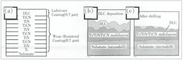
The performance of DLC coating is similar to that of diamond coating, and it is also widely used in PCB processing. However, the internal stress of the DLC coating is relatively large, and the bonding force between the coating and the substrate is poor, so a transition layer can be added between the DLC and the substrate. Ueng et al. prepared Ti/TiN/TiCN/DLC coating on a φ0.4mm micro drill, as shown in Figure 6, the tool life was increased by 2.5 times; when 2500 holes, the hole wall roughness was 0.40mil (1mil=0.0254mm), TiN coating is 0.58 mil, uncoated is 0.95 mil. For different PCB dielectric layer resin materials, such as epoxy resin with high filler content, polyimide with strong adhesion, and polytetrafluoroethylene with strong creep, DLC can add different elements to the coating. Improve performance to suit various performance sheet processing.
Adding N and W elements in the preparation of DLC coating can significantly improve the wear resistance of the coating. Kao control Zr-C: H: Nx% (the content in the text is atomic fraction if not otherwise specified) coating micro-diamond N content When it is 17%, the tool life is increased by 5 times; the W content of the aC:Wx% coating micro-drill is 8.8%, and the tool life is increased by 2.24 times, as shown in Figure 7. Luo Jinlong and others applied SHC super-hard coated micro-drills to flexible PCB processing, and the service life is twice that of uncoated micro-drills. DLC coating has a very low friction coefficient, can effectively avoid resin sticking to the knife, and promote chip removal at the same time, it is widely used in flexible boards and aluminum substrates.
Due to the mature preparation process of PVD coating, the cost is lower than that of diamond coating, and it is easy to mass produce, so it has attracted more and more attention in practical application. For the processing depth-to-diameter ratio ≥18:1, the cutting temperature is higher for the plates containing aluminum base and ceramic base, and the coating containing Al can greatly improve the high temperature hardness and oxidation resistance of cutting tools; processing plates with higher hard filler content , Si-containing coatings can be selected, because Si can play a role in solid solution strengthening and grain refinement. Frank et al. compared TiCN, TiAlN, TiAlCN, CrAlN, and amorphous carbon coating five kinds of micro-drills. Among them, TiAlN coating has the best oxidation resistance, the lowest wear and the smallest adhesion.
He Tianlu and others prepared CrAlTiN gradient coating micro-drills by magnetron sputtering method, which increased the life span by 3 times. Kang et al. studied the influence of Si element on CrN-based coatings. When the Si content is about 9%, the hardness of CrSiN and CrAlSiN coatings can reach the maximum 35GPa and 55GPa. Among them, CrAlSiN coated micro-drills can achieve a lower friction coefficient and the best Excellent drilling performance. Chu et al. prepared a CrWCN coating on a φ0.25mm micro-drill by sputtering. The friction coefficient is 80% and 53% lower than that of Cr and Cr2N, and the hardness is 70% and 25% higher than that of Cr and Cr2N. The life of PCB processing Compared with uncoated micro-drills, the increase is 4~5 times, as shown in Figure 8. In addition, more and more companies and research institutions are applying PVD coating to micro tools. Shanghai Kerui Material Technology Co., Ltd. designed a super hard and wear-resistant Cr-based composite coating for PCB, using CrN as the base layer, and the outer layer is AlCrTiN coating. The composite coating has high hardness, toughness and low friction coefficient features.
2. Ti6Al4V Titanium Alloy
Ti6Al4V titanium alloy is widely used in aerospace industry, shipbuilding, medical treatment, metallurgy and other industries. Its main processing characteristics are:
- The cutting deformation coefficient is small, the contact stress of the rake face is high, and the tool wear is serious;
- Tool sticking is prone to appear on the rake face, which dulls the cutting edge of the fine tool and increases the cutting force;
- High cutting temperature and poor thermal conductivity.
At present, the coatings of micro-tools for micro-cutting of titanium alloys mainly include diamond coatings, Al coatings and cubic boron nitride (CBN) coatings, among which the main component of diamond coatings is C element, which has lower chemical properties with titanium alloys. Affinity, low friction coefficient. Compared with traditional cutting, the cutting temperature is lower in the micro-cutting process. Although the diamond coating has poor high temperature resistance, it has better thermal conductivity, so it is widely used;
However, there will still be a small temperature rise on the tool that will cause chipping or micron-level cracks, so appropriate cutting parameters must be selected.
Wang Yongxu found through Abaqus simulation that in the process of milling Ti6Al4V with a φ0.5 mm diamond-coated micromilling cutter, the stress concentration on the contact surface of the load and the tool and the interface between the coating and the substrate is the most serious. The stress distribution on each cutter surface is approximately triangular. After the cracks in the layer propagate to the interface, they will move along the interface to peel off the coating; during the process of milling titanium alloy, there are obvious stress concentration areas on the sidewalls of the microgrooves and accompanied by burrs. There is an increase in the element stress value, and there is a ripple in the tool feed.
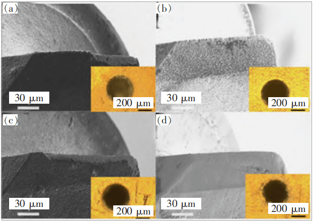
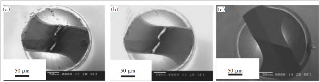
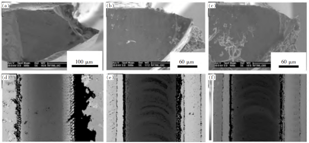
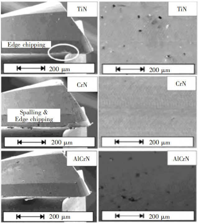
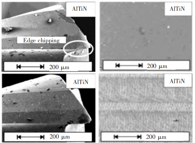
Aslantas et al. compared the cutting performance of φ0.5 mm NCD, AlCrN, TiN coated milling cutters and uncoated milling cutters for cutting Ti6Al4V. Tool wear is mainly based on abrasive wear, chipping and chip buildup, and found 3 types of coatings. In the layer, only NCD did not show built-up edge, but if the wear of the tool diameter is concerned, the AlCrN and TiN coatings are the lowest. Both NCD and AlCrN milling cutters have coating peeling. Among them, the NCD coated milling cutter has been subjected to the substrate. Cobalt removal treatment, so the exposed substrate will be more severe in milling wear than uncoated, as shown in Figure 9.
In addition, NCD and AlCrN have the lowest surface roughness, and TiN and AlCrN have the lowest burr width. Thepsonthi et al. analyzed the milling process of Ti6Al4V with a CBN coated milling cutter with a diameter of 0.508 mm through simulation and experiment. The CBN coating effectively reduces the roughness, but promotes the formation of top burrs; the simulation found that the back cutter of the CBN coated micro milling cutter The wear area and average edge temperature of the face and rake face are lower than that of the uncoated micromilling cutter.
CBN is a kind of hardness second only to diamond, but its high-temperature oxidation resistance is better than that of diamond. It can better adapt to the high-temperature processing environment of titanium alloy. However, CBN has problems such as difficult control of cubic phase ratio and small deposition area during the preparation process. Therefore, it is still in the research stage.
3. Aluminum Alloy
The output of aluminum alloy occupies the second place among metal materials. It is widely used in the main parts of automobiles and aerospace materials, such as engine block, cylinder head, wheel hub, etc. Its main processing characteristics are:
- Good ductility, easy to cause sticking phenomenon;
- High cutting temperature;
- The modulus of elasticity is small, and the flank will be elastically restored during the cutting process, and the weakly rigid micro tools are more likely to vibrate, and the milling process is prone to vibration marks.
At present, the commonly used coatings for micro-cutting of aluminum alloys mainly include diamond and DLC coatings.
Li Zhaoguang et al. found that in the process of drilling φ0.05 mm aluminum alloy deep holes, the eccentricity of drilling easily causes the tool to bear alternating loads, and the weak point of the strength of the micro drill is at the root; under the action of cutting force, the weak point of the tool strength is the edge of the cutting edge. The safety factor of the knife edge will decrease as the feed per tooth increases.
Torres et al. found that in the process of milling aluminum alloy with a φ0.3 mm diamond-coated milling cutter, the x-axis and y-axis forces are more symmetrical in the positive and negative directions, which greatly reduces tool deflection, improves tool life, and reduces aluminum alloy Burrs and improve the surface quality, as shown in Figure 10. Heaney et al. [38] found that φ0.3 mm fine-grained diamond-coated milling cutters reduce tool adhesion and reduce 75% of the main cutting force and 90% of the axial force in the process of cutting aluminum alloy.
Wu et al. studied the cutting of aluminum alloy 6061-T6 with DLC-coated milling cutters, and the average cutting force decreased by 16%, and found that the distance between the edge of the DLC coating before and after cutting to the tool reference line reduced the tool wear by 17% compared with uncoated , But there is still more aluminum adhesion at the cutting edge.
At present, the conventionally used simple single-layer multi-element aluminum-based nitride coating has no obvious effect on aluminum alloy micro-cutting. For example, AlCrN, AlTiN and other coatings will have different degrees of sticking phenomenon, so the current multi-layer coating is used More, the surface layer is a carbide coating with a low affinity for aluminum, and then Cr and CrN are used as the transition layer to increase the bonding force of the carbide coating. For example, Cr/WC coating has been applied to aluminum alloy processing.
4. Nickel-Based Alloys
Nickel-based alloy is a high temperature alloy with high strength and certain oxidation and corrosion resistance at high temperatures of 650~1000 ℃. It is widely used in aerospace and nuclear industries. Its main cutting characteristics are:
- High cutting temperature and poor thermal conductivity (only 1/3~1/5 of 45 steel).
- There are a large number of hard points, and the hardness will increase with the increase of temperature at 0~600 ℃, which will cause bounce and severe abrasive wear during the processing of the weak rigid micro drill and milling cutter.
- The work hardening of nickel-based alloy is severe.
- It has a high affinity with most metals, and the chips are easy to adhere to the material. According to the research of Sharman et al., CrN has good chemical compatibility with nickel-based alloys, so try to avoid using coatings containing CrN phases. Floor.
In summary, the commonly used coatings for nickel-based alloys are TiN-based coatings containing Al and C elements, such as TiN, TiCN, and TiAlN coatings. In addition, related studies have shown that DLC coating can also effectively improve the processing quality of nickel-based superalloys.
Uran et al. compared AlTiN, AlCrN, TiAlN+AlCrN, TiAlN+WC/C, DLC and other five kinds of φ0.786 mm coated milling cutter cutting performance of nickel-based alloys, found that AlCrN, TiAlN+AlCrN adhesion is serious, TiAlN +WC/C, DLC help reduce built-up tumors.
But the most different from traditional milling is that under the condition of low feed and low depth of cut, the tool will have a high wear rate; and the blunt radius of the tool will increase in the initial stage of drilling, and then it will show a downward trend.
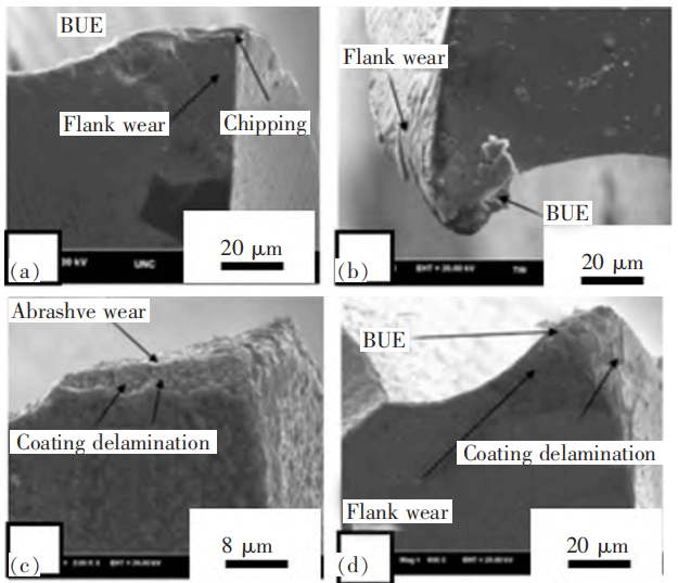
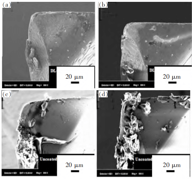
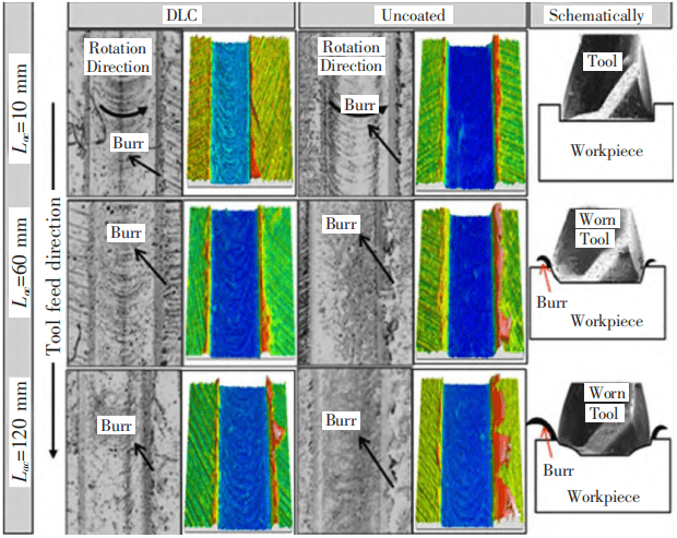
Uran et al. found that in the cutting of 718 nickel alloy with a DLC coated milling cutter of φ0.708 mm, the main wear of an uncoated milling cutter of φ0.708 mm is abrasive wear and diffusion wear for different cutting parameters, and is accompanied by The generation of cutting edge.
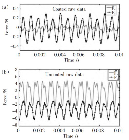
DLC coating can effectively reduce the built-up edge and cutting force, as shown in Figure 11. In the early stage of processing, the surface roughness and burr width of the nickel alloy processed by the uncoated cutter and the DLC coated milling cutter are similar, but in the later stage, the DLC coating The burr width and surface roughness of the layer milling cutter are significantly lower than those of uncoated, as shown in Figure 12.
5. Hardened Steel
Hardened steel refers to various hardened die steels, bearing steels, high-speed steels, etc. that have been heat treated with a hardness above 50HRC. They are commonly used to prepare various parts with high hardness and wear resistance, such as molds, bearings, gears, etc. , Its main processing features are:
- Hardened metamorphic layer is prone to appear, increasing tool load;
- The cutting deformation is uneven, and the jagged stripes produced will cause the tool to vibrate, which is easy to cause chipping of the micro tool;
- The cutting temperature is high and the thermal conductivity is poor (only 1/7 of 45 steel), which can reach 900 ℃.
6. Other Materials
As the application range of micro-cutting becomes wider and wider, difficult-to-machine soft metals (gold, silver, copper alloys, etc.), ceramic materials, silicon, etc. have also entered the scope of micro-cutting. Diamond coating has achieved good processing results in soft metal processing, polymer materials (acrylic, epoxy, etc.), glass and ceramic processing. DLC coatings with similar performance to diamond coatings can also be tried. In consideration of cost and preparation conditions, various TiN and CrN-based multi-element coatings and multilayer structure composite coatings with high hardness and high temperature resistance are gradually being applied.
The surface quality is the best, and the cutting quality of the TiAlN coating is poor, probably because the TiAlN coating micromilling cutter has the most surface droplets. Shin et al. combined the arc ion plating and sputtering methods to prepare a φ2.0 mm CrSiN coated milling cutter, and found that the friction coefficient decreased with the increase of Si content; during the cutting process of the CrSiN coating with Si content of 9.3%, the cutting The force and flank wear width are greatly reduced compared with CrN coating.
Romanus et al. compared the cutting performance of sintered ZrO2 ceramic materials with CBN, MCD, NCD and hard carbon coating 4 kinds of φ1.0 mm coated micromilling cutters, and found that the diamond coating has the best cutting performance, but it is prone to peeling. The average surface roughness of the processed workpiece is less than 60 nm, and the cutting distance is greater than 2 m.
Wu et al. used φ0.5 mm and φ0.2 mm diamond-coated micromilling cutters to mill photovoltaic silicon wafers, and found that the diamond coatings of two diameters inevitably flake off. It is speculated that the main reasons for diamond flake off are Two:
First, when the tool is in contact with the material, due to the sudden change in torque and cutting force, the strong impact load causes the diamond coating to fall off;
Second, the fatigue stress in the cutting process, because milling is an intermittent cutting, continuous fatigue impact can also easily cause the coating to peel off.
7. Conclusion
By summarizing the common problems of macro-cutting, combining the key points of micro-cutting theory, and then selecting the coating of micro-drilling and milling tools suitable for each material for different processing materials. In the future, the coatings for high-end PCBs are mainly diamond coatings and DLC coatings. However, considering the preparation cost and difficulty of preparation, various PVD multi-layer TiN-based and CrN-based coatings will be applied to PCB processing;
The diamond coating may develop towards the nanocrystalline level in the future. Nanocrystalline diamond can control the cutting edge sharpness of the micro drilling and milling cutters while ensuring the hardness and wear resistance. Due to the large number of processing materials, the micro cutting tools PVD coating will gradually develop from a binary coating to a multi-layer nano-coating.
Integrating the principles of economy and processing adaptability, developing the best coated micro-drilling and milling tools for different materials, and continuously improving the quality of micro-cutting is of great significance to the development of micro-parts and microelectronic products.
Research on Coating of Micro Drilling and Milling Tools (I)